LDR Photoresistor: Create a Twilight Switch
How does a device know it’s nighttime? Thanks to the photoresistor (LDR). This passive component sees its resistance vary according to the light received, allowing for the creation of intelligent automatic systems.
⚡ Quick Answer
A photoresistor (LDR) is a sensor whose resistance decreases sharply with light intensity. It allows for the easy creation of light-sensitive devices, such as a twilight switch, by integrating it into a voltage divider circuit connected to an analog input.
Safety: Always disconnect the power supply before modifying the wiring.
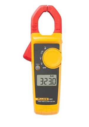
Fluke 323 Digital Clamp Meter (True RMS, 400A AC)
🛠️ The essential tool for this project.
The Setup
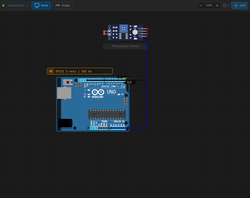
Wiring Table
| Component Pin | Arduino Pin | Color |
|---|---|---|
| VCC | 5V | Red |
| GND | GND | Black |
| Signal (AO) | Pin A0 | Blue |
Arduino Code
const int ldrPin = A0;

void setup() {
  Serial.begin(9600);
}

void loop() {
  int lightLevel = analogRead(ldrPin);
  Serial.print("Light Level: ");
  Serial.println(lightLevel);
  delay(500);
}
Live Demonstration
The magic of the photoelectric effect
I have always found it fascinating to be able to “sense” the environment of our circuit. The photoresistor (LDR for Light Dependent Resistor) is often the first analog component one discovers. Unlike a button which is simply ON or OFF (digital), the LDR offers us a whole range of subtle values, from complete darkness to full sunlight.
Inside this sinuous-looking component is cadmium sulfide. When photons (light particles) hit this material, they release electrons, which instantly decreases the component’s resistance. This is the beauty of quantum physics accessible for a few cents on a breadboard!
The secret of the circuit: The voltage divider
You may have noticed in our setup that the LDR is not alone: it is always accompanied by a standard resistor (usually 10kΩ). Why? Because the Arduino cannot read resistance; it can only read voltage (between 0V and 5V).
By placing the LDR and the fixed resistor in series (what is called a voltage divider), we transform the variation in resistance into a variation in voltage. It is this voltage that enters pin A0 and which the analogRead() function converts into a number between 0 and 1023. This is one of the most crucial concepts to master in analog electronics.
Concrete use cases and workbench tips
Throughout my experiments, I have seen dozens of ways to use an LDR:
- Drawer alarm: Hide the circuit in a drawer. As soon as someone opens it, light enters, the value drops, and the Arduino triggers a buzzer!
- Solar tracker: By placing two LDRs separated by a small wall, you can program a servomotor to always orient itself towards the strongest light source, ideal for optimizing solar panels.
- Calibration tip: Ambient light changes all the time. Instead of hardcoding a value (e.g.,
if (lightLevel < 500)), program a 5-second calibration phase when the Arduino starts (in thesetup) so that it records the max and min values of the room. This will make your circuit robust everywhere!
Electronics is above all about adaptation. Don’t hesitate to tweak the values in your code to find the perfect trigger threshold for your room.
To delve deeper into power management, don’t forget to check our article on Ohm’s Law.