5 PLC Programming Languages to Master Industrial Automation
Today, we are going to talk about three-phase motors and PLC programming.
Three-phase motors are a type of electric motor that uses three phases of alternating current to operate. They are commonly used in medium and high-power applications, such as compressors, pumps, and ventilation motors.
PLC programming, or Programmable Logic Controller programming, is the process of defining the actions and functions that a PLC must perform. The IEC 61131-3 standard defines five PLC programming languages: LD (Ladder Diagram), FBD (Function Block Diagram), SFC (Sequential Function Chart), ST (Structured Text), and IL (Instruction List). The choice of programming language depends on the PLC manufacturer and the application in which it will be used.
To write and test the code before downloading it to the PLC, PLC development software is used. The IEC 61131-3 standard also establishes rules to ensure the safety and reliability of PLC programming.
Here is a list of the 5 most commonly used PLC development software tools:
- Ladder Logic Simulator – This software is specifically designed for ladder language programming and is easy to use thanks to its intuitive interface.
- Siemens Step 7 – This software is the most widely used for Siemens PLC programming and supports LD, FBD, SFC, and ST languages.
- Rockwell Automation Studio 5000 – This software is designed for Rockwell Automation PLCs and supports LD, FBD, SFC, ST, and IL languages.
- Schneider Electric Unity Pro – This software is designed for Schneider Electric PLCs and supports LD, FBD, SFC, and ST languages.
- Mitsubishi GX Developer – This software is designed for Mitsubishi PLCs and supports LD, FBD, SFC, and ST languages.
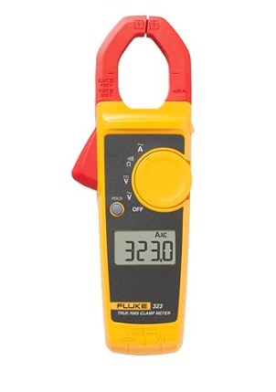
Fluke 323 Clamp Meter (True RMS, 400A AC)
🛠️ The indispensable tool for this project.
ace-pre-wrap »>
Here is a short and simple code example for each PLC programming language:
LD (Ladder Diagram):
L1 M1 M2
|_____|
|
L2
In this example, L1 and L2 represent logic contacts and M1 and M2 represent relay coils. If L1 is closed, M1 will be activated and M2 will be deactivated. If L1 is open, M1 will be deactivated and M2 will be activated.
FBD (Function Block Diagram):
f1 : TON
IN : IN1
PT : PT1
Q : Q1
In this example, f1 is a TON (On-Delay Timer) function block. IN1 is the block input, PT1 is the preset time, and Q1 is the block output. If IN1 is true for a duration longer than PT1, Q1 will be true.
SFC (Sequential Function Chart):
Step1 Step2
| |
| |
|_______|
|
Step3
In this example, Step1, Step2, and Step3 represent steps in a process. When Step1 is completed, the process moves to Step2. When Step2 is completed, the process moves to Step3.
ST (Structured Text):
IF IN1 THEN Q1 := TRUE;
ELSE Q1 := FALSE;
In this example, IN1 is a logic input and Q1 is a logic output. If IN1 is true, Q1 will be set to true. Otherwise, Q1 will be set to false.
IL (Instruction List):
LD M1
AND M2
ST Q1
In this example, M1 and M2 are bit-type (binary) memory words, and Q1 is also a bit-type memory word. LD M1 loads the value of M1 into an internal register. AND M2 performs a logical AND between the value in the register and the value of M2. ST Q1 stores the register value in Q1.
That concludes this overview of three-phase motors and PLC programming.