Drone Propulsion: Understanding Brushless Motors and ESCs
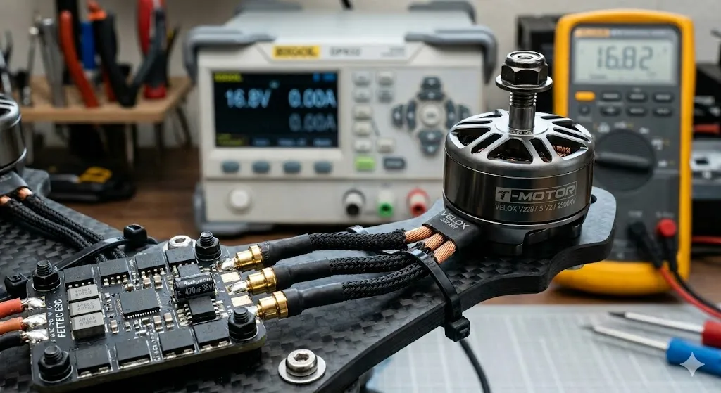
Understanding Drone Motorization: ESC, Brushless Motor and PWM Signal
A drone’s propulsion system is a feat of electronic engineering. For a quadcopter to fly stably, it is not enough to just spin the motors: ultra-fast communication must be orchestrated between the flight controller (Arduino/ESP32) and the Brushless motors. Here is how this power chain works.
⚡ Quick Answer
Drone motorization relies on the Brushless motor and ESC (Electronic Speed Controller) pair. The Brushless motor offers an exceptional power-to-weight ratio without friction, while the ESC transforms DC current from the battery into synchronized three-phase pulses, thus managing rotation speed via protocols like DShot or PWM.
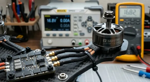
The Brushless Motor: Why 3 wires?
Unlike the direct current (DC) motors found in small toys, a drone motor is a permanent magnet synchronous motor. It has no brushes (hence the name “Brushless”), which reduces friction and wear.
Since there is no physical contact to reverse polarity, it is the ESC (Electronic Speed Controller) that must create a rotating magnetic field. To do this, it successively powers three phases (often denoted U, V, and W). It is this ultra-fast electronic switching that allows reaching tens of thousands of revolutions per minute with surgical precision.
The ESC: The Power Conductor
The ESC has two major roles:
- Conversion: It transforms the DC current from the LiPo battery into three-phase current.
- Interpretation: It listens to commands from the flight controller via a control signal.
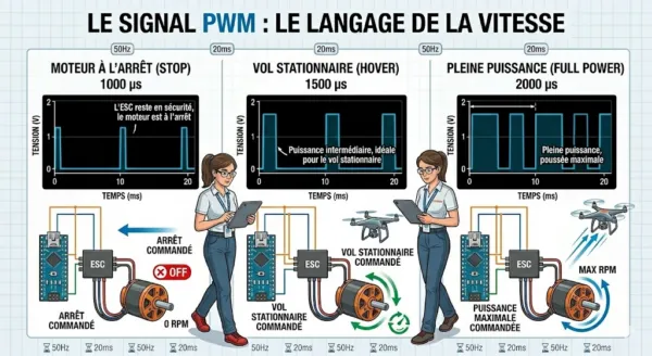
The PWM Signal: The Language of Speed
To tell the ESC how fast to spin, the Arduino uses Pulse Width Modulation (PWM). It is not the voltage that changes, but the duration of a pulse sent every 20 milliseconds (50Hz).
- 1000 µs (microseconds): The ESC stays in safety mode, the motor is stopped.
- 1500 µs: Intermediate power, ideal for hovering.
- 2000 µs: Full power, maximum thrust.
Control Code Example (Arduino)
Using the Servo.h library, controlling a drone motor becomes as simple as controlling a standard servomotor:
#include <Servo.h>

Servo esc;

void setup() {
  esc.attach(9); // PWM signal on pin D9
  // Arming procedure: the ESC needs to receive the minimum signal at startup
  esc.writeMicroseconds(1000);
  delay(2000);
}

void loop() {
  // Sending a speed command (e.g., 1200µs for a slow test)
  esc.writeMicroseconds(1200);
}
Troubleshooting and Assembly Tips
- Reverse rotation direction: If your motor spins in the wrong direction, simply swap two of the three wires between the ESC and the motor. There is no fixed color order; it’s all in the phase sequence.
- Calibration: Every ESC model has its own range. It is crucial to perform a “high throttle / low throttle” calibration so that your flight controller knows the exact limits of your motorization.
- Vibrations: A poorly secured motor or an unbalanced propeller generates electronic “noise” that the gyroscope will struggle to filter, making the drone unstable.
By mastering this chain — from the PWM signal to three-phase switching — you have understood the very essence of modern electric flight. The next step consists of coupling these motors to a PID feedback loop for automatic stabilization.
🧠 Selection: Related Topics
Our algorithm found these articles that share a strong thematic proximity with your current reading:
- 🔗 How to Build a Drone with Arduino (Complete DIY Guide 2026) (Affinity: 80%)
- 🔗 SG90 Servomotor: Controlling Precise Angular Movements (Affinity: 78%)
- 🔗 HC-SR04 Ultrasonic Sensor: Measuring Distances with Arduino (Affinity: 75%)
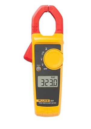
Fluke 323 Clamp Meter (True RMS, 400A AC)
🛠️ Expert Opinion: A precise measuring tool is essential for checking the continuity of your Brushless windings and avoiding any short circuits.