Arduino 101: Blink Your First LED (The Ultimate Guide)
Welcome to the exciting world of programmed electronics! If you’ve just unpacked your first Arduino kit, you’re probably wondering where to start. The “Blink” project is the universal initiation rite for every future engineer or maker. It’s the “Hello World” of hardware.
⚡ Quick Answer
Arduino 101 is the ideal starting point for learning programmable electronics. The ‘Blink’ project (making an LED flash) allows you to master the structure of an Arduino code: setup() for initialization and loop() for the repetitive execution of control instructions.
In this Arduino 101 tutorial, we aren’t just going to blink the LED built into the board. We’re going to build our own circuit on a breadboard to understand how electricity flows and how code physically comes to life. I’ve prepared this guide to be as clear as possible, even if you’ve never held a wire in your life.
Safety Note: Before any manipulation, make sure your Arduino is disconnected from your computer. Never work on a live circuit to avoid accidental short circuits.

Fluke 323 Clamp Meter (True RMS, 400A AC)
🛠️ The essential tool for this project.
Required Materials
- 1x Arduino Uno (or compatible).
- 1x Red LED (or any other color).
- 1x 220Ω Resistor (Essential for protecting your LED).
- 2x Connecting wires (Jumpers).
- 1x Breadboard.
Understanding the Wiring
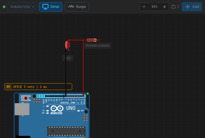
Wiring an LED is simple but requires respecting the direction of current flow. An LED has two legs: the Anode (the longest, the +) and the Cathode (the shortest, the -). For this setup, we will control the LED via pin 12 of the Arduino.
Why a 220Ω resistor? (If you want to go deeper into the calculation, check out our guide on Ohm’s Law). The Arduino delivers 5V on its outputs. Without a resistor, this current is too strong for a standard LED and could burn it out instantly. The resistor limits the flow of electrons to ensure a long life for your component.
Connection Table
| Component | Component Pin | Destination | Wire Color |
|---|---|---|---|
| Arduino Uno | Pin 12 | Resistor Input | Red |
| Resistor | Output | LED Anode (+) | – (Direct connection) |
| Red LED | Cathode (-) | Arduino GND | Black |
Source Code (C++)
Copy and paste this code into your Arduino IDE software. It uses two fundamental functions: setup() which runs once at startup, and loop() which repeats indefinitely as long as the Arduino is powered.
/*
 * Arduino 101 Tutorial: Blinking an LED
 * Author: Electrotuto.com
 */

const int ledPin = 12; // We are using digital pin 12

void setup() {
  // We set pin 12 as an OUTPUT
  pinMode(ledPin, OUTPUT);
}

void loop() {
  digitalWrite(ledPin, HIGH); // Send 5V to the pin (Turns on the LED)
  delay(1000);                // Wait for 1000 milliseconds (1 second)

  digitalWrite(ledPin, LOW);  // Cut the power (Turns off the LED)
  delay(1000);                // Wait for another 1 second
}
Simulation Result
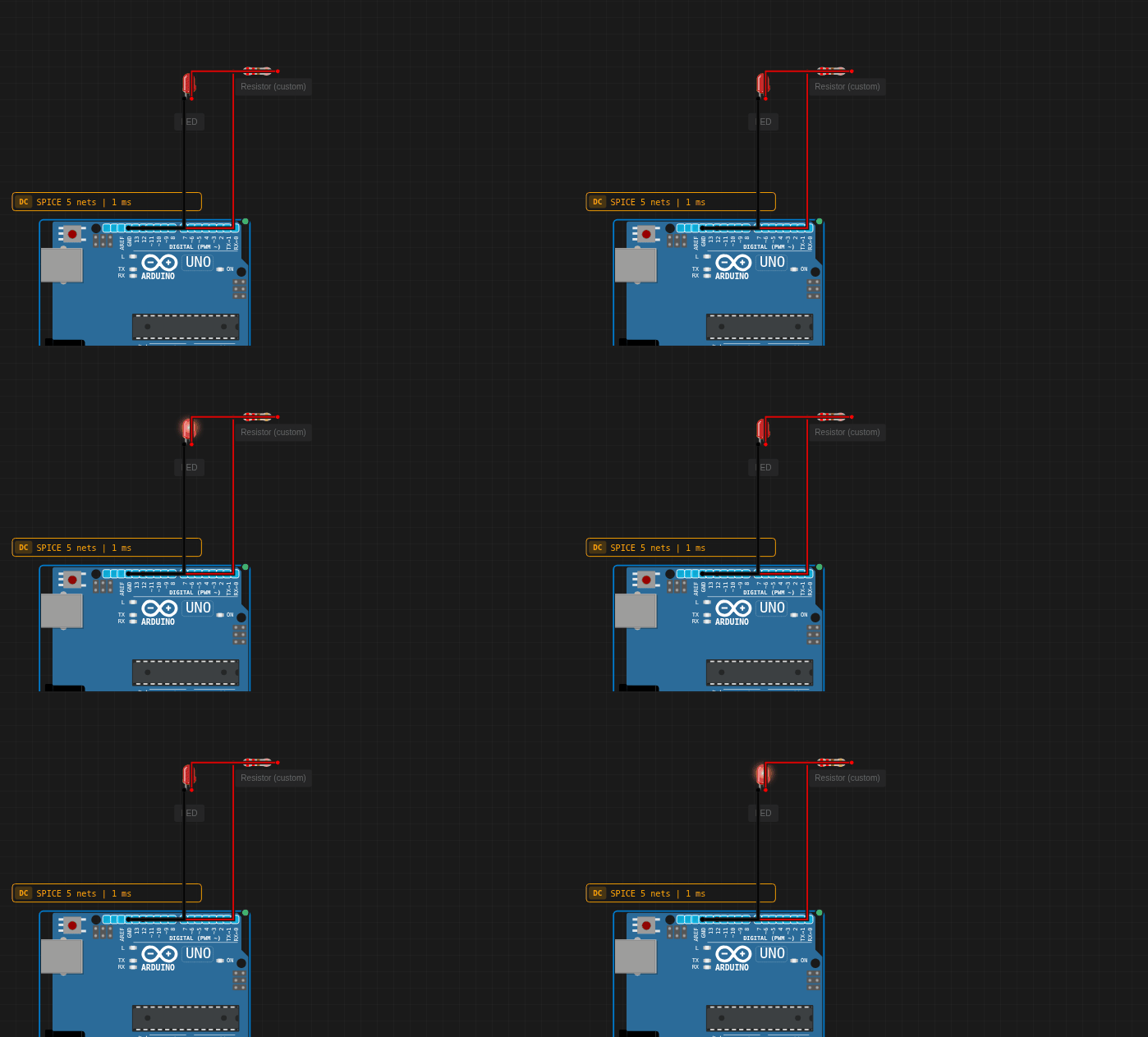
Once the code is uploaded, you should see your LED blinking with perfect regularity. Here is what you should get in your setup:
Conclusion and Next Steps
Well done! You’ve taken the first step in your journey into electronics. You now know how to wire an LED, use a protective resistor, and control a digital output through code.
Challenge for you: Try changing the value in delay() to make the LED blink faster (e.g., 200 ms) or to create a heartbeat effect. What happens if you plug the LED into pin 11 instead of 12 (don’t forget to change the code!)?
Any questions? A wiring issue? Leave a comment below, I respond to all makers!